| home | introduction | secondary cage | mirror box | truss | rocker box |
| how to make a truss dob |
|
part 4: The truss and the clamps
Poles
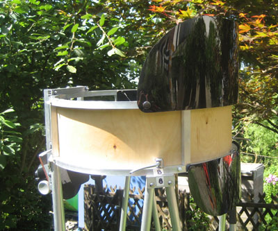
For my 22" Dob, I use 22x1.2 mm poles, for the 16" Dob 20x1.2 mm. Whenever weight and packing size are not of ultimate importance, an 8-pole truss is preferable over a 6-pole truss.
|
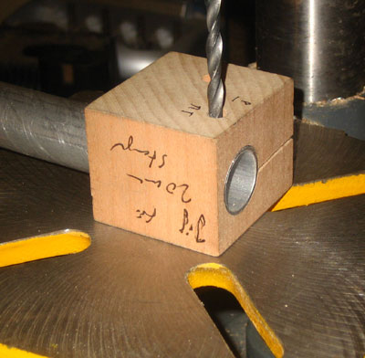
For drilling straight and centered holes into poles, it is useful to make a drill jig as shown to the right. |
 |
Upper clamps
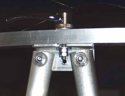
| For attaching the poles to the secondary cage, I use a system that I saw for the first time on a Dob by Achim Strnad. The poles are paired with aluminum angles, that have a slot for insertion of the bolt of quick-release levers. | 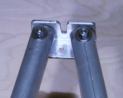 |
| The levers remain permanently
attached to the upper cage, such that there are no loose parts. The joint is
absolutely solid and the tubes cannot be moved relative to each other (in
contrast to some commercially offered "solutions"). Such a solid connections
with no possibility of lateral movement is a requirement for a solid truss.
For my first telescopes, I used quick release levers of bicycle wheels. In the meanwhile I found nice industrial levers that are offered for instance from the companies Norelem or Genoma. |
|
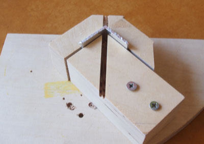
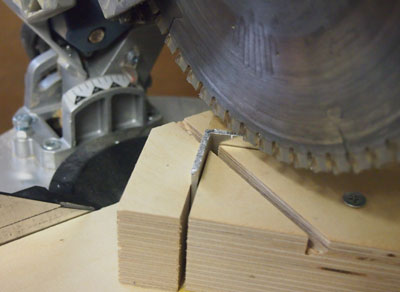
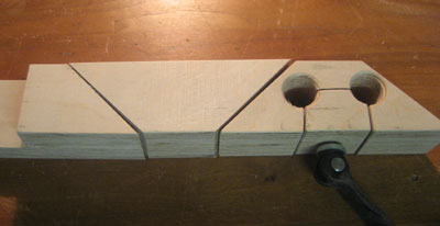
| The slots in the aluminum angles are made using jigs, that allow to cut the aluminum reproducibly and, above all, in a safe way, on a miter saw. | 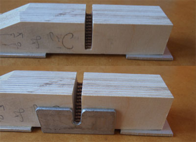 |
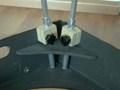
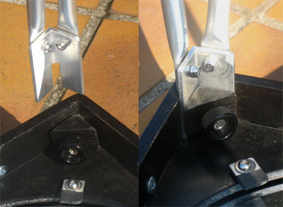
| Another possibility for the upper
clamps is shown to the right (alternatively also often with ball ends). The
problem here is the difficulty to fit all ends simultaneously into the
clamps and to get everything really tight.
We had such connectors on the 20" Dob of our local club and I had also used it initially on my 14" Dob. After I had tested this system in practice, I quickly changed to the system shown in the above section. |
 |
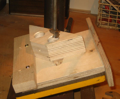
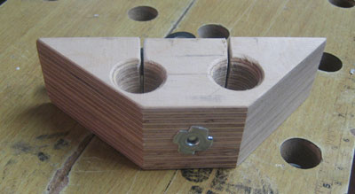
Lower clamps
| I have used different alternatives for the lower clamps and finally settled with clamps similar to those of Stathis Kafalis' Kyklopas. Each clamp holds two poles and the clamping blocks are glued into the corners of the mirror box and mirror baffle. This reinforces the corner of the boxes and allows for excellent force transmission without deforming the box. | 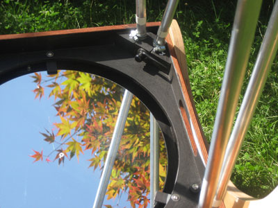
|
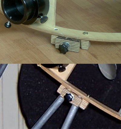
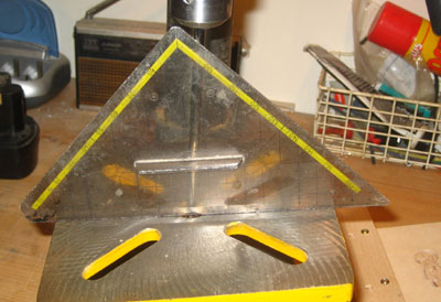
| Another possibility for lower clamps is shown to the right. It is particularly suited for smaller Dobs, as for instance my 10" Travel Dob.
The poles are connected in pairs using slotted aluminum angles. The angles are locked to the corner of the mirror box using wooden triangles and a bolt.
The slots in the aluminum angles are made using again a jig. The aluminum angles, already cut to the desired length, are fixed in the jig and the slot is cut out with a miter saw. Both width and depth of the slot can be reproduced precisely. |
|
| Single blocks (as in the image to the right) or poles that are directly screwed onto the sides of the mirror box tend to deform the mirror box side walls, which leads to unwanted back lash during tracking. |
|
| The angle of the poles relative to the mirror box is determined from the constructions plans. The table of the drill press is adjusted accordingly. Small outward or inward tilts of the poles are avoided or neglected. |
 |
| The blocks of the clamps are made by gluing together two layers of 21 mm plywood. The blocks are cut into shape on the miter saw. |
 |
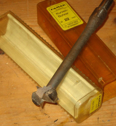
| For drilling the holes, I use
Förstner or even more sophisticated milling bits. I use a mechanical stop on
the drill press table to fix the blocks. This allows quite precise drilling
of the holes for the aluminum poles.
Finally, the hole for the bolt of the lever is drilled and the chock of the clamp is cut out with the jig saw.
|
|
| The quick release clamps have an M5 bolt, which is bolted into the captive nuts on the back of the block. | 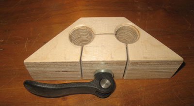
|
Two complete set of blocks. |
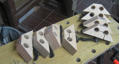 |
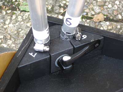
| The blocks are glued into the mirror
box corners, yielding the most rigid joint. Poles and holes in the clamps are numbered. This maintains collimation of the tube assembly to a certain degree over breakdowns and setups. Still, I check collimation after every setup, but usually only minor tweaks of the collimation screws are required. The poles have little sleeves consisting of stainless steel hose clamps, which allow to adjust the length of the truss precisely. Within certain limits, the position of the focal point of the telescope is therefore adjustable. |
 |
![]()
| home | introduction | secondary cage | mirror box | truss | rocker box |