| home | introduction | secondary cage | mirror box | truss | rocker box |
| how to make a truss dob |
|
part 2: The secondary cage
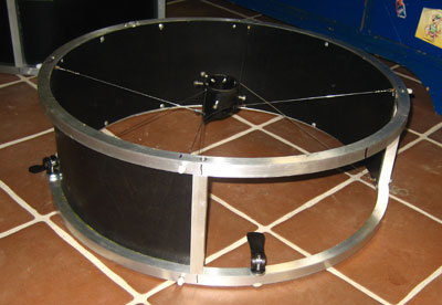
The secondary cage can be designed as a single-ring or as a two-rings unit. Single-ring is of advantage if low weight and small dimensions are important, as for instance for a travel Dob (see here). Two-rings are generally more suitable for "daily use", as they are much more sturdy and offer simpler solutions for the light baffles (such as here and here).
|
The inner diameter of the secondary cage should be large enough such that the light cone will not be cropped. As a rule of thumb, I choose a diameter according to that of the primary plus 7 cm. This will give you even some buffer for mounting components on the secondary cage such as filter slides, focuser baffles, etc. Alternatively, you can have the minimum front aperture calculated by the program Newt. |
|
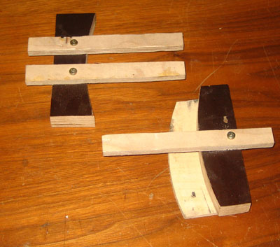
Bending aluminum rings in a vice
I use a method of which I read for the first time on the web page of Jan van Gastel and which is used in the meanwhile quite often by other telescope makers.
For bending square aluminum tubes, I make wooden templates of hard wood (such as oak or the hard wood ply wood shown on the right). The usual birch plywood is not as suited as it is relatively soft and deforms under the high loads. The radius of the templates should be somewhat smaller than the desired radius of the final rings. As a rule of thumb, you can start with a radius that is 10% smaller. The outcome may vary, however, depending on the aluminum tubing and the hardness of the templates (so it ends up with try-and-error). I cut the templates with the jig saw (take care for a vertical cut) or with the router. To achieve good handling of the templates, I attach a small piece of crap plywood at the bottom of one of the templates and three small pieces on the top (see right picture). |
 |
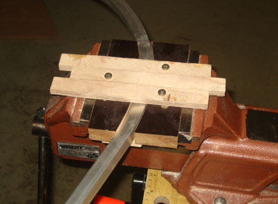
| For bending you need a massive vice
of sufficient size. During the bending process, the tube will be advanced
only two to three centimeters each time, pressed, opened, advanced, etc.
Take care that the tubing does not get distorted. Generally, this method can be used to bend aluminum square tubing up to 15x15x1.5 mm or 10x20x1.5 mm. You should achieve the complete bending in a single round, as you cannot do the bending in small steps (e.g. for subsequent improvement). To achieve a lasting plastic deformation of the aluminum material, a minimum deformation is required, that cannot be compensated by the material's elasticity. Do not heat the tubes for bending, as this will result in uneven curvature! You may fill the tubing with sand to avoid inward bending of the sides of the tubing, but I don't do this. |
 |
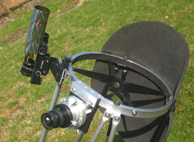
| You can connect the ends of the rings by small aluminum inserts. For making a two-ring-cage, the two rings can be connected by short aluminum tubes. To connect them to the rings, I glue small wooden blocks into the connections and use wood screws. |
Planking of the secondary cage
For planking of the secondary cage, I use thin 1.0 to 1.5 mm modeling plywood, which can be readily bent perpendicular to the outer grain direction. The plywood can be glued onto the aluminum rings and fixed with small screws in pre-drilled small holes. It is recommended to do the planking not in a single step.
|
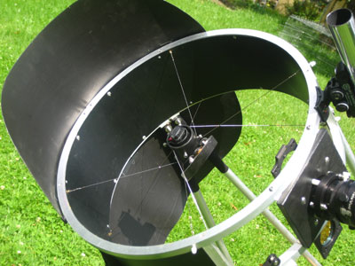
For my larger Dobs, I ended up with
wire spiders. Unlike solid spiders, wire spiders can be made involving
triangles with really large base length, which results in extreme rigidity.
Wire spiders further minimize thermal effects on spider vanes, which are
treated here.
The spider is made to connect excentrically to the secondary holder. Additionally the spider legs are crossed, which increases the effective base length of the involved triangles. I use four wires for a spider, which are threaded through at the secondary holder. |
 |
|
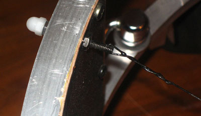
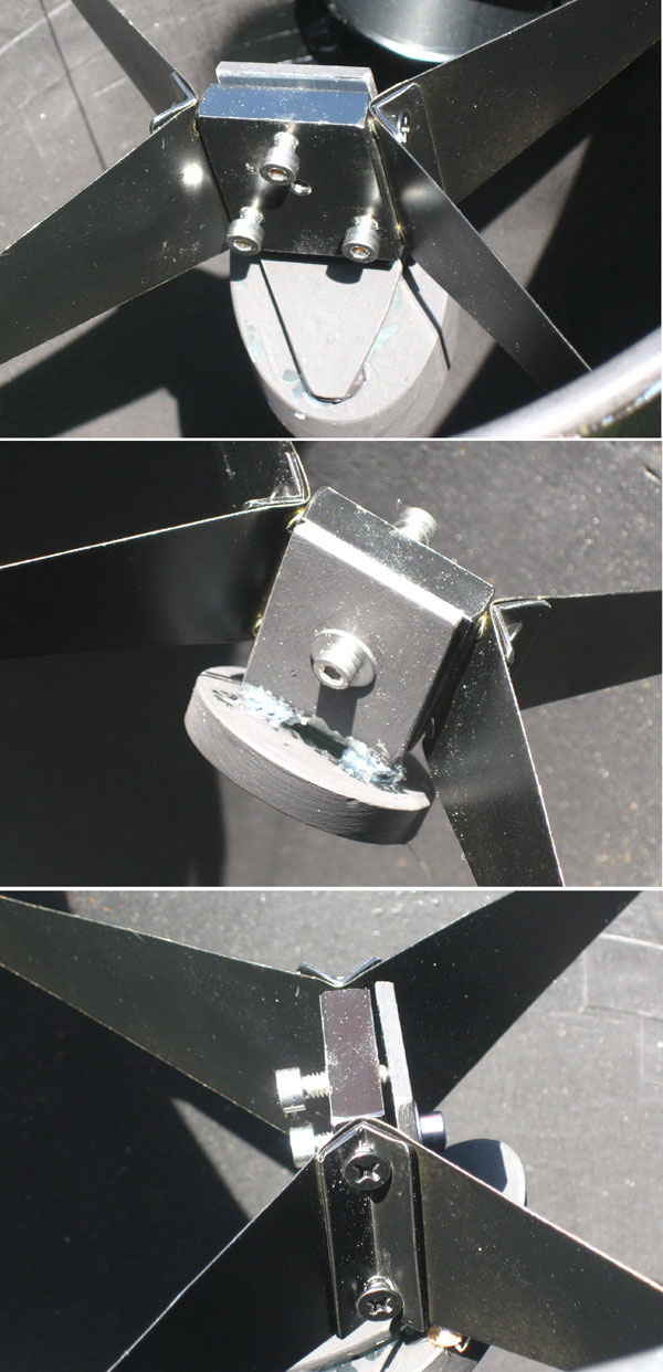
The wires can be connected to the cage either by eye bolts (M4) or via
small bolts with a small hole at the end to thread the wire. For wiring, I use 0.8 mm spring steel wires (www.conrad.de). |
 |
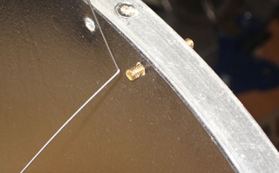
| Alternatively the bolts can be attached to the ring also by use of so-called shank nuts. These are bolts with an inner thread. | 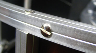 |
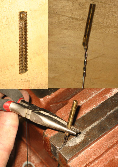
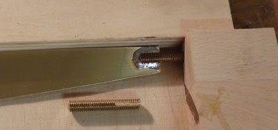
| The bolts are best made of M4 brass
threaded rods, which are easier to drill. For 15mm aluminum profiles, 30 mm
bolts are a good size.
The bolts are flattened with a file and then a 1.5 mm hole is drilled at one end. At a later point, the wires are passed through these holes, bent and fixed in the vise. With pliers, the bolts are turned and the wires are twirled. Try to to do this a few times on scrap wire. |
 |
| Twirling becomes a piece of cake, if you make yourself a tool of a scrap piece of aluminum. Make a small slot with a saw and twirl the wires under tension. | 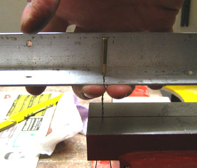 |
| At the outer secondary holder tube, the wires are just passed and bent. You will need four wires for one spider. | 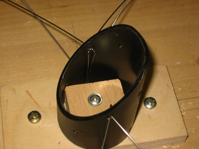 |
|
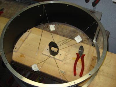
It is recommended to fix the cage and the secondary holder on a jig prior
to assembling the spider. This greatly facilitates inserting the wires and
determining their correct length. Then you determine the correct lengths
of the wires and bend them accordingly. After this step, the wire is taken out of the cage (number the wires!) and connected to the bolts (see above). |
|
| Then the spider is taken back into the secondary cage and the bolts are fastened with nuts from the outside. | 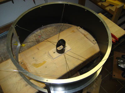 |
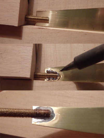
| Finally, the ends of the wires are
fixed by soldering.
It is very important to cross the wires, as this increases the effective length of the base of the involved triangles. The crossing points are fixed by thin wires and soldering, which again increases the overall strength of the spider. A properly made wire spider finally has a stability clearly beyond that of a conventional spider of same thickness/obstruction/weight (pick whatever is important to you). |
 |
| For smaller telescopes, wire spiders become a hassle and there is no need for their superior strength. Here a conventional spider made of sheet metal can be of advantage. The same holds for mono ring upper assemblies, where a large base length cannot be realized. | 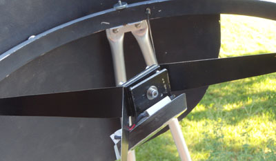 |
| I have made conventional spiders of 0.3 mm brass sheets, which is sufficient for Dobs up to 12". This sheet metal can be cut even with sturdy scissors. | 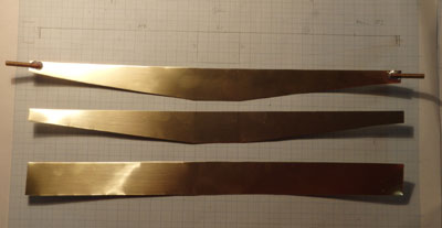 |
| For a single spider, I cut two sheets, which will be connected in the middle by two aluminum plates. These plates serve as the fixed part of the secondary holder later (Sackett-Type, see below). This design yields an excentric spider. | 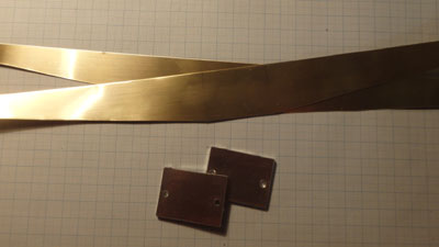 |
| One potentially weak point with
conventional spiders is the connection of the spider arms to the ring. This
can be done by gluing the spider sheets into slotted bolts using a
two-component adhesive. This may work well (but does not necessarily so). If
not carefully done, the adhesive may not stick solidly to the smooth metal
sheet. A simple and nevertheless very robust alternative is soldering the brass sheets into slotted brass pins. This can be done even with regular solder and a conventional tip. |
 |
| Conveniently, this can be done in a
small jig, which keeps the spider arm and the slotted bolt in place. During
soldering, take care that the solder flows well into the slot and is evenly
spread on the brass sheet. This
yields a very robust connection of the spider to the upper ring (virtually
unbreakable, even in a vice |
 |
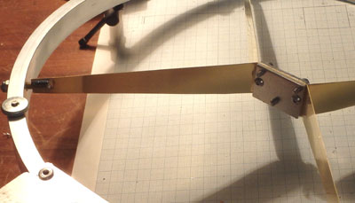
| This is a conventional spider mounted
in a single ring upper assembly.
|
 |
Secondary Holder
| The purpose of the
secondary holder is to keep the secondary rigidly at a defined position in a
defined orientation. Secondaries dangling on a long threaded rod of whatever
size make my toe nails coil up (as we say in Germany
My favorite type of secondary holder is a simplified version of the holder
made by Stathis Kafalis for his Kyklopas
(the "mother" of all 24-inch Dobs
The secondary mirror is then glued with silicone (~ 1mm thickness) onto the bottom plate. The silicone bonding is safe.
|
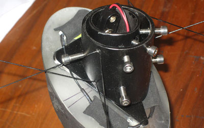 |
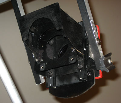
| The inner part of the secondary holder is collimated via 4 bolts (right) on the outer tube and fixed via two bolts (left). An additional bolt at the upper right prevents the inner part from falling out of the outer tube. Collimation via six bolts may seem complicated, but in practice it is not. The whole unit is absolutely rigid and the collimation of the secondary is done once and is not part of the daily collimation routine. | 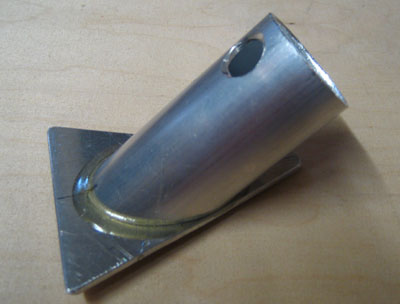 |
| The lower plate of that inner tube is glued to the tube with epoxy (UHU plus endfest) and cured for 10 min. in the oven at 180°C. For good bonding, holes are drilled through the plate and widened from the outside. The glue creeps into these holes during bonding and yields a strong connection. I tried to separate a test piece by fixing the plate in a vise and trying to rip of the tube. No chance. | 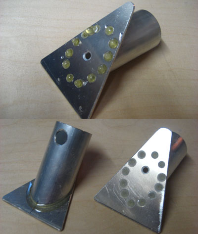 |
Other Secondary Holders
| This type of secondary holder can also be combined with a conventional spider as shown on the right in the first version of my 14-inch Dob. | 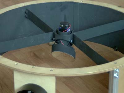 |
| An alternative type of
secondary holder is shown on the right. The design is by Ross Sackett
and this type is particularly suited for smaller Dobs. It is easy to make,
rigid (again no secondary dangling on a single long threaded rod), and easy to
collimate. Alternatively, the spider arms can be as well mounted between two aluminum plates, as shown further above. That type is a bit easier to make. |
 |
| Optional heating of the
secondary under humid conditions may prevent fogging. I use three power
resistors with square profile (because of the profile, not because of the
power), which are glued with heat transfer past onto the secondary and fixed
with two drops of epoxy on the sides. The wiring is threaded through the
inner tube of the holder. A battery pack with two AAA cells can be inserted
into the inner tube and is secured against falling out with the battery clip. The heating has a power of 0.5 W for my 14-inch and 1 W for my 22-inch Dob. Using a voltage of 3 V, this corresponds to three resistors of 6 and 3 Ohms, respectively (power = voltage squared divided by total resistance) |
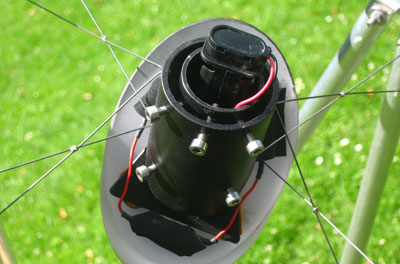 |
| There is a small hole in
the bottom plate for the wires.
|
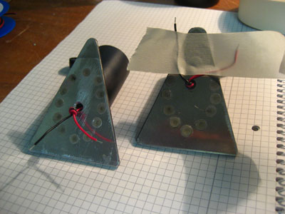 |
| As heating elements I use three resistors with square profile, which are connected to the secondary by heat conducting paste and fixed by two little dots of epoxy. | 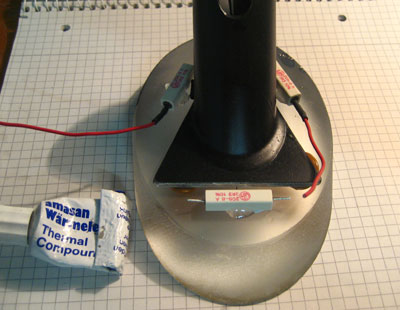 |
| The resistors can be further isolated against air by small foam pieces, yet the heat transfer to the glass is much more efficient than to air, anyways. | 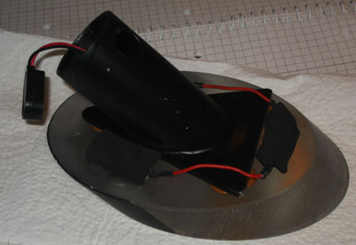 |
| The heater runs on a two AA battery pack, which is during use inserted into the secondary holder and secured by the battery clip. | 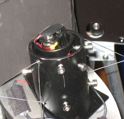 |
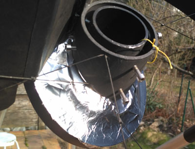
| Bare metal surfaces radiate hardly in
the infrared. Radiative cooling of the secondary mirror below
ambient temperature
and in particular under the dew point can therefore be
largely reduced by covering the exposed rear side of the secondary with aluminum
tape. Thermal equilibration of the secondary to ambient temperature is still
maintained by the surrounding air. This passive means against radiative cooling considerably helps to reduce the necessity of actively heating the secondary mirror. In fact, I haven't been forced to used the active heating system after installing this passive protection on my 22" Dob's secondary. |
 |
| A good material for
secondary baffles is transparent 0.8 mm PE material, which is offered in the
gardening department for making greenhouses (see Tobias
Schöller's page).
This material is painted from one side with black dispersion paint (quite resistant to
abrasion). The most stressed parts are further protected with black tape to
avoid abrasion.
These baffles are attached to the rings of the secondary cage by patent fasteners. |
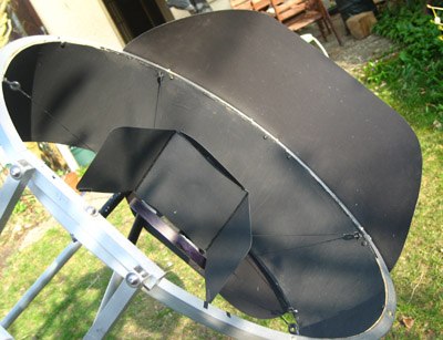 |
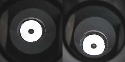
| The secondary baffles should be as
large as necessary and as small as possible to minimize wind resistance. The
minimal size can be determined by trial. Simply look through the focuser and
mark the most extreme parts of the baffles that are still visible. You may
reduce the diameter of the focuser hole to the size of the maximal eyepiece
field stop being in use. More about baffling is on the page of my 22" Lowrider here. If you observe under stray light or even with street lights nearby, you should be more generous with the size of the baffles, as light falling onto the barrel or barlow element of eyepieces will cause stray light as well. |
 |
| For making the secondary baffles, the PE sheets are fixed on a board and the black paint is rolled on it. Usually, two applications are sufficient. | 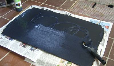 |
| The paint that worked best for me was a regular dispersion paint. The coat is quite resistant to abrasion. Only the most stressed parts were additionally covered with black tape. | 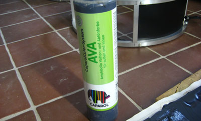 |
| The baffles are attached to the secondary rings using push buttons as used for camping gear or rain coats. They are riveted to both the PE sheets and the aluminum rings. | 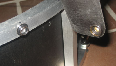 |
Focuser baffle
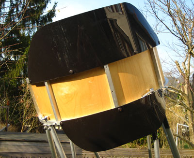
| The size of the secondary
cage baffles can be significantly reduced by a proper baffle at the focuser.
The opening of this baffle should be large enough to allow passing of all
the light from the secondary not only on axis, but also over the required
field. The focuser baffle does not need to be as elaborate as that of my lowrider Dob on the right. Even a single baffle is already very efficient.
All in all, the baffling of the entire Dob should make sure that while looking through the focuser (even at an angle), only mirrors and black surfaces are visible. You will notice that also the focuser board needs to have a black back and should have a certain minimum size. |
|
On which side to mount the focuser?
| One which side should
one mount the focuser? Left or right? And what means "left" and "right" on a
telescope? Let us define as "left" that side, which faces East, when the Dob points toward South, and "right" the side, which then faces West. My own Dobs have the focuser on the "right" side, while most commercial Dobs have it on the "left" side. There had been several discussion on the internet groups whether people prefer to "push" or to "pull" while tracking the stars with their Dobs. Whether you use push or pull mode depends solely on the side where the focuser is mounted. As philosophical such discussions may be, they do not come to the point. The point is rather: Which eye do you prefer for observing? Somebody, who observes preferentially with his left eye, is better up with the finder and the focuser on the right side of the telescope. On the other hand, an observer who prefers his right eye, has a better time while being on the left side of the telescope. Try it out! I observe solely with my left eye.
Hence all my telescopes have the focuser and finders on the right side. It's
as simple as that |
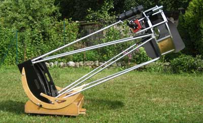
Focuser on the RIGHT side (my 22"):
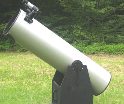
Focuser on the LEFT side (GSO 12")
|
![]()
| home | introduction | secondary cage | mirror box | truss | rocker box |