| home | introduction | secondary cage | mirror box | truss | rocker box |
| how to make a truss dob |
|
part 3: The mirror box
The mirror cell
Plop by David Lewis and Toshimi Taki is a very useful little program for designing mirror cells. It calculates the deformation of a mirror in its cell using finite elements and optimizes the support points to minimize these deformations. The newest version even considers lateral forces for an inclined mirror. The mirror cells, that I have built, are in particular 6-point cells, as for instance for the relatively thick 16" GSO mirrors from Taiwan, and 18-point cells for my thinner 14" and 22" mirrors. Robert Houdart gives useful information on the design of the lateral support of mirrors.
| My first "real" mirror cell was of
the (in the meanwhile outdated) Kriege-Berry type, where the mirror is
moved during collimation within the cell and held in place by a sling.
This type has several serious disadvantages over more modern types of cells. First, the mirror changes its position within the cell during collimation, which prevents optimal lateral support of the mirror and, in the case of using a sling, may introduce lateral forces. Second, a mirror supported by a sling is not fixed laterally and can hence move, which may easily lead to complete loss of collimation. |
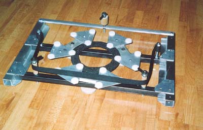 |
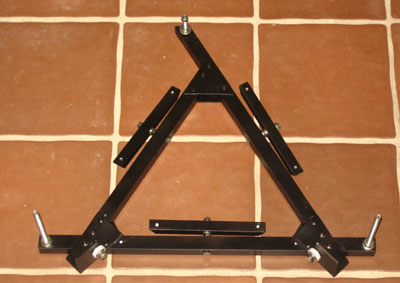
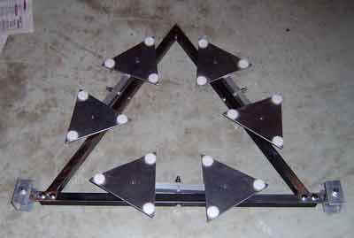
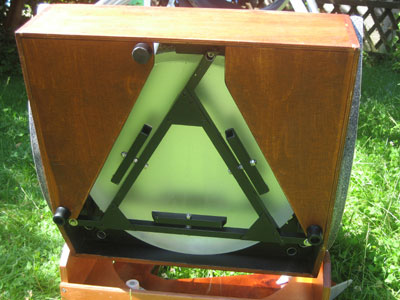
| A considerably more advanced concept
involves a cell, in which the mirror is fixed laterally. Collimation is achieved by
moving the mirror together with the entire cell. In my big Dobs, I use
a triangular cell, which can be made of welded steel (above image) or of
riveted square aluminum tubing (lower image). The support beams for 6- and
18-point supports are attached at the sides of the triangle. They can also
be integrated into the beams of the triangle, as shown by Ulli
Vedder. It is sufficient to move only two of the corners for collimation and attach the third corner permanent (with only minimal freedom of rotation) to the mirror box. |
|
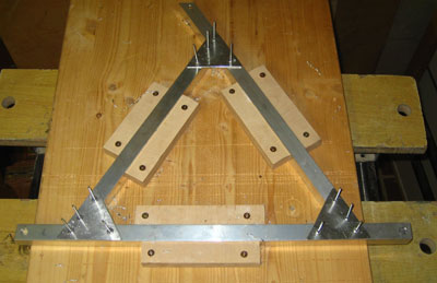
| Before mounting the mirror cell, all
holes need to be drilled into the tubings.
For mounting, it is recommended to use a jig, where all parts can be fixed. The holes for the junction plates are drilled. Then the plates are glued to the cell with UHU plus endfest, fixed with 4mm rivets and cured for 10 min at 180°C (first one side, then the other). This yields a very stable connection. |
 |
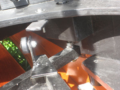
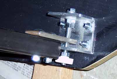
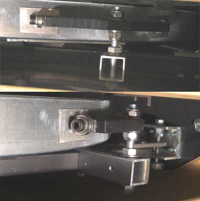
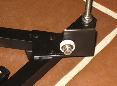
| An advanced possibility of an
adjustable support point is shown to the right and based on a mirror cell
designed by Ulli Vedder.
Here, the support point is adjusted by a threaded bolt, which can freely rotate in some kind U-shaped holder attached to the mirror cell. The cell is attached to this bolt by a small thread in a steel plate, which is again adjustable to allow for its precise positioning and to prevent the thread from blocking. During collimation, the cell is slightly rotated, which is due to the only short thread in the steel plate not a problem |
 |
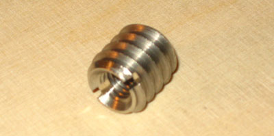
| The threaded inserts can be mounted by first drilling a hole of the nominal diameter of the thread (here 8mm for M8) as shown in the right block. The hole is widened to the diameter of the core of the insert over the length of it and then beveled (left block). | 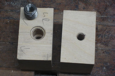 |
| To make sure that the insert is mounted straight, the insert is threaded onto a bolt and then screwed into the wood. | 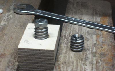 |
| Then you remove the bolt. | 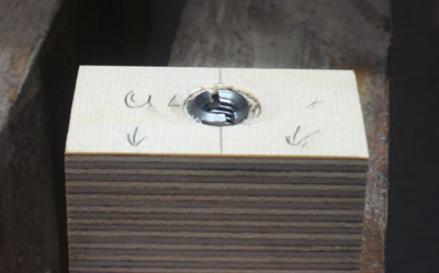 |
Lateral support
| The mirror should be supported
laterally at the line of gravity using steel ball bearings. Lateral support
points should be positioned at 45° to the vertical axis, when using a single
pair of support points, or symmetrically distributed around these points
when using a a whiffle tree support. A useful little program is Robert Houdart's Mirror Edge Calculator. To prevent direct steel-glas contact, the steel bearings can be covered with plastic tubing. Alternatively, thin aluminum plates glued onto the mirror sides will also protect the glass. To the right, a whiffle tree lateral support is shown. |
 |
| Here is a simple support using only
two ball bearings.
In both cases, the height of the support points is adjustable, e.g. by threaded rods (above) or a by a long hole in which the support bolt of the ball bearing can be moved (below). |
 |
Mirror box
| The most important
property of a mirror box is stiffness, as it connects the mirror to the
truss tube.
A mirror box can be made of relatively thin plywood, given that there are suitable reinforcements. The mirror box to the right (for a 16") or even the box of my 22" Dob are made of 12 mm plywood with reinforcements made of 9mm plywood. Useful locations of braces are below the lower clamps where the forces of the truss are transmitted to the box. Double clamps that are glued into the corner allow a very solid transmission of the forces without deforming the weaker sides of the mirror box. A complete mirror baffle above the mirror as well as two additional bracing boards at the lower side of the box yield a very rigid frame to support the mirror cell. The lower front corners of the mirror box can further be cut off a bit. This allows to put the box even lower in its rocker and to minimize height. |
|
| The cut-out of the mirror baffle can be recycled as a mirror cover. You better use a jig saw rather than a router for cutting out the baffle, as the width of the gap will be smaller. |
 Alt Alt |
Simple joints for the mirror box
| The mirror box can be made without the use of ugly screws by using simple corner joints that can be made on the table saw. | 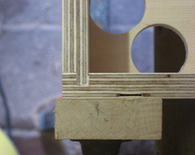 |
| Here are the parts of the sides of the mirror box with the joints and with grooves for the mirror baffle and the reinforcement boards at the bottom side of the box. | 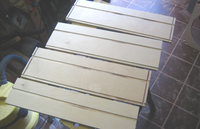 |
| The box is assembled using only wood glue. Take care that the box is square before pressing! | 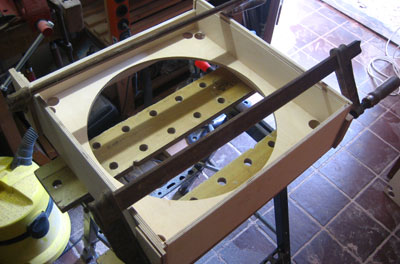 |
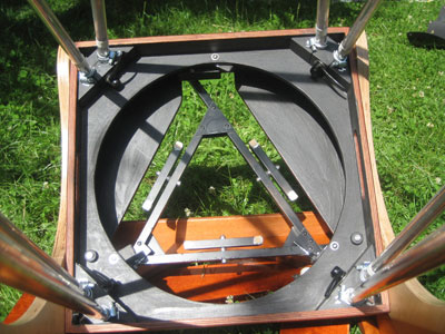
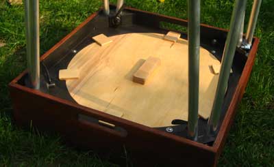
Installing the mirror cell
| First you determine the precise location of the three wooden blocks that hold the mirror cell. | 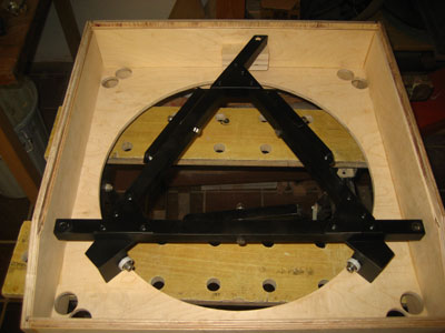 |
| The blocks are glued into the box. The cell is fixed to the upper block, which is not used for collimation. Only the two blocks in front are used for collimation and have the threaded inserts for the collimation bolts. | 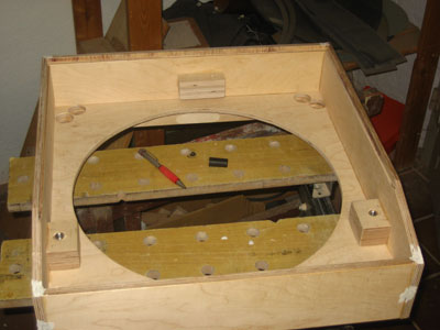 |
| Then the two boards can be glued into the back of the box for reinforcement. | 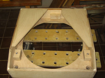 |
| Finally, the clamps for the trussed are glued into the corners of the mirror cell. | 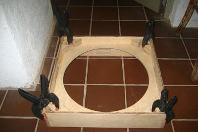 |
| Finished. | 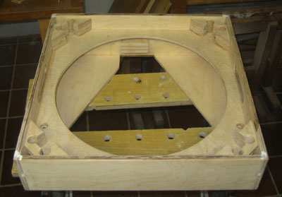 |
![]()
| home | introduction | secondary cage | mirror box | truss | rocker box |