filter transmission spectra
Introduction Links spectra: OIII UHC H-beta other
![]()
Properties of interference filters
The spectral properties of filters are often displayed in a transmission spectrum. In such a spectrum, the percentage of the light that is transmitted by the filter is plotted vs. the wavelength.
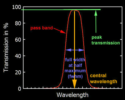
Nebula filter let light pass only within a narrow pass band. This pass band is characterized by its central wavelength, the peak transmission within the pass band, the width of the pass band, characterized by the full width at half maximum (fwhm), and the steepness of the edges of the pass band (the steeper, the better). The ultimate goal for a nebula filter with given bandwidth is a filter with a peak transmission close to 100%, complete blocking outside the pass band, and a quasi-rectangular shape of the pass band.
In contrast to colored glass filters, in which the blocked light is absorbed, the filter action of interference filters is based on constructive and destructive interference on a series of alternating thin dielectric layers. The blocked light is not absorbed, but reflected by the filter.
An excellent introduction to design and theory of interference filters is here.
Spectral properties of "ideal" nebula filters
Ideal nebula filters should have high transmission in the range of the specified emission lines and complete blocking in the remaining spectral range.
|
HeII |
468.6 nm |
|
H beta |
486.1 nm |
|
[OIII] |
495.9 nm |
|
[OIII] |
500.7 nm |
|
[NII] |
654.8 nm |
|
H alpha |
656.3 nm |
|
[NII] |
658.4 nm |
|
[SI]I |
671.7 nm |
|
[SII] |
673.1 nm |
Within the pass band, the transmission of the filters should therefore be well above 90%. The spectral width of the filter should be as large as necessary not to cut the emission lines, but not larger to avoid transmission of unwanted continuum light. This is best achieved when the edges of the pass band are as steep as possible. In order to be compatible also with fast optics, the pass band should have some buffer at the red side of the pass band to allow for a slight shift of the pass band (see below). Outside the pass band, the filter should block into the red and blue range as far as possible, at least as far that the range of sensitive scotopic vision between around 420 nm and 600 nm is covered.
What are the important emission lines of HII regions and Planetary Nebulae? For visual observing, these are only a few lines: the OIII emission lines at 501 nm and 496 nm (with the 496 nm line having one third of the intensity of the other line) and the H-beta emission line at 486 nm. The H-alpha emission line at 656 nm is not relevant for visual Deep Sky observing (see here).
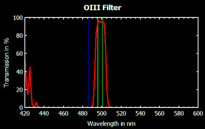
The ideal OIII filter should be broad enough to transmit the two OIII emission lines at 496 and 501 nm (green) with sufficiently high percentage. The filter shown above (Lumicon) has a transmission of above 95% on both OIII lines and a half width (fwhm) of only 12 nm. This is about the minimal band width that allows the two lines to be transmitted without significant loss.
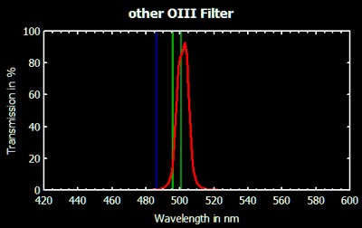
The OIII filter shown above (Baader) with a bandwidth of only 9 nm is narrower than the Lumicon and should therefore be better in blocking unwanted continuum light. This filter has, however, a transmission of only 86% at the OIII emission line at 501 nm and of only 21% at the (fainter) OIII emission line at 496 nm. It therefore severely cuts transmission of the specified OIII lines. Nevertheless, this filter can do a good job on bright OIII objects, such as for instance the veil nebula or on bright planetary nebula, or under heavy light pollution. Under good conditions, however, the detection of faint OIII objects is noticeably hampered as compared with the Lumicon filter.
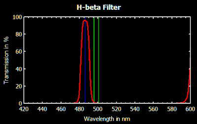
As an H-beta filter has to transmit only a single emission line at 486 nm, the band width can be smaller than with an OIII filter. The filter shown above (Lumicon) has a transmission of almost 96% on the H-beta line with a band width of only 9 nm.
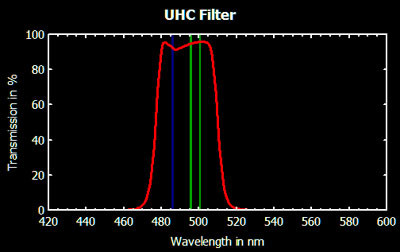
UHC filters transmit both the OIII and the H-beta lines and are therefore necessarily broader. The filter shown above (Astronomik) has transmission values of 92%, 95%, and 96% for the H-beta and the two OIII emission lines and a half width of 33 nm. As evident from the transmission spectrum, the band width of the filter could as well be 5 to 6 nm smaller without affecting transmission of the tree emission lines. This was considered with the newer series of UHC filters by Astronomik, which have a bandwidth of only 28 nm with transmission values on the emission lines similar to the filter shown above. The newer series of UHC filters by Lumicon are even slightly better with a bandwidth of 24 nm and transmission values above 95% on the three emission lines.
Influence of "leaks" on filter performance
While filters intended for photography should be blocked over a wide spectral range, such a wide blocking is not necessary for filters intended for visual use, as long as peak transmission and pass band width are optimal. The graph below shows the transmission spectrum of a Lumicon OIII filter (white), that has additional "leaks" in the range below 430nm. The blue line shows the relative spectral sensitivity of the dark-adapted eye. The red area is the transmission of the filter weighted with the spectral sensitivity of the eye. A comparison of the relative areas shows quite clearly that such "leaks" outside regions of sensitivity of the eye are marginal and that instead the optimal (i.e. smallest possible while maintaining full transmission on the lines) width of the pass band is the decisive factor for filter performance.
The lower graph shows two different UHC filters that have comparable transmission of the relevant H-beta and OIII lines, but different widths of the pass bands of 27 and 58 nm, respectively. Both filters transmit therefore equal amounts of the "desired" light (and have hence a similar "signal"), yet the broader filter transmits about twice the amount of "undesired" light (corresponding to twice the "noise". The "signal-to-noise ratio" of the broader filter is therefore only about half of that of the narrower filter.
Is a red pass band advantageous for a UHC filter?
A few years ago, I would have answered clearly that this does not matter at all, unless you are going into photography.
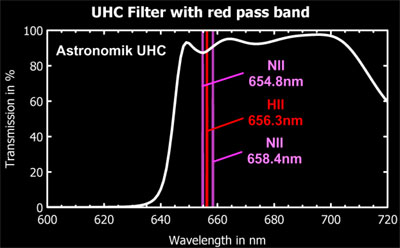
In the meantime, I am no longer a 100% sure about this. Many of the old and faint PNe emit a significant amount of their light in the NII lines at 654.8 and 658.4nm (see, for instance here), which are immediately adjacent to the H-alpha line at 656.3nm. The H-alpha line is accompanied by the H-beta line, which has only one third of its strength, but is placed in the visually better accessible blue spectral range. The NII lines do not have such counterparts in the blue range.
For extremely faint objects, that emit mainly in the NII lines, and under perfect observing conditions, a UHC filter with optimal pass band in the red spectral line for the NII and H-alpha lines could be the filter of choice. It does not matter much, if the pass band is open toward the red end, as the spectral sensitivity of our photoreceptor cells may serve as a "natural" cut-off.
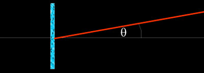
Influence of non-normal incidence on the position of the pass band
The nominal position of the pass band of an interference filter is usually given for normal incidence of light. If the filter is used between mirror/objective and eyepiece (as usual), we deal with *nearly* normal incidence of the light on the filter and the pass band of the filter is not changed. In some situations, however, we have to deal with deviations from normal incidence, e.g. when
|
|
the filter is tilted by a certain angle |
|
|
a filter is used between eyepiece and eye (e.g. with binoculars or for filter blinking) as the viewing angle behind the eyepiece is much wider than the light cone before the eyepiece |
|
|
we use very fast optics (see below) |
Under such conditions, the pass band changes:
|
|
it becomes blue-shifted, i.e. shifted to shorter wavelength |
|
|
its peak transmission decreases slightly |
|
|
the shape of the pass band changes and the bandwidth increases slightly |
For deviations from normal incidence, θ, smaller than 25°, the shifted position of the pass band, λθ, can be calculated by
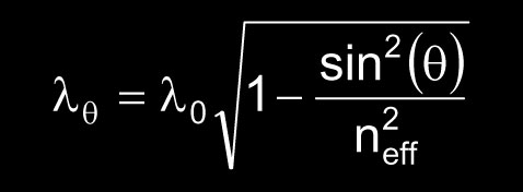 ,,
we≈
,,
we≈
where λ0 is the peak position at normal incidence and neff is the effective refractive index of the filter. Typically, interference filters have neff of 1.45 or 2.0, depending on the dielectric material being used, which ultimately depends on the precise application and the required specifications. Filters with wider pass bands (such as typical UHC or broadband filters) are usually based on high-index spacers ( neff ≈ 2.0). Filters with extremely narrow pass bands and steep sides require low-index spacers ( neff ≈ 1.45). As a trade-off, they have a somewhat more pronounced wavelength shift than the former.
Here is an example of a narrow band interference filter with low-index spacers (Baader OIII), measured under different angles of incidence, θ.
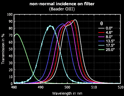
The blue-shift of the peak, the decrease of the peak transmission, and the change of the pass band profile are all discernible in this graph.
Influence of fast optics on the pass band
So what's the point about fast optics and interference filters? Slow optics have a steeper light cone than fast optics, such that the light passes the filter closer to normal. For fast optics, the mean angle of incidence θeff can be calculated for the (mean) 71%-zone of the objective/mirror (f-number of an f/4 optic is 4)
tan (θeff) = 0.71 d / 2f = 0.71/(2*f-number)
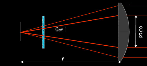
For an f/4 telescope, this yields θeff = 5.1° and a shift of the pass band (at λ0 = 500nm) of approximately 1 nm, in agreement with the measurements shown above. For the edge rays, this shift increases to about 2 nm.
Therefore, with an f/4 telescope, the pass band shift is small, even for a narrow low-index filter, as even for fast telescope optics, the light cone is still relatively steep. Only for extremely narrow filters or for filters, where the specified emission line is close to the red edge of the filter, this pass band shift may affect performance. The situation is different, if a filter is used between eyepiece and the eye. Here the viewing angle is much larger and hence the pass bands shifts considerably off-axis. This is visible as a color change (towards blue in the most simple case) towards the edge of the field of view.
Aging and edge deterioration of filters
Older filters may age and undergo slow deterioration starting at the edge. As far as I know, this has been observed with some (not all) of the older laminated filters sold by Lumicon, but in at least one case also with newer series (my own Lumicon H-beta filter, left filter in the lower image). Presumably, this is related to moisture and inadequate storage of filters, as there are filter from before 1995, which are not affected.
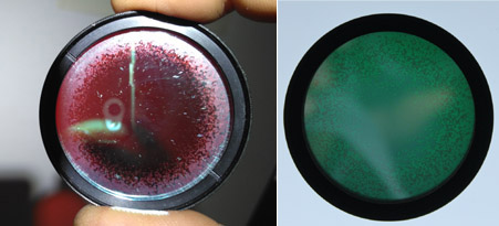
Edge deterioration of two interference filters (left H-beta, right OIII)
In the photospectrometer, transmission spectra taken from the center of the filter look normal, while there is a shift of the passband to the red and a reduced transmission towards the edge.
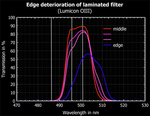
Transmission spectra of the OIII filter in the upper right image
This spectral behavior could be due to a slight swelling of the dielectric layers of the filter during the aging process. As long as the aging process does not affect the entire filter, such filters may still perform reasonably well in the telescope. With the OIII filter in the right image, we successfully observed Abell 31 without severe limitations.
![]()
Filter transmission spectra
Besides optical quality, the transmission characteristics determine the usefulness of nebula filters. Therefore, transmission spectra are very helpful in deciding which filter to buy.
The spectra below are filter transmission spectra of filters of my own and of others. All spectra were obtained with a Hewlett-Packard G1103A (8453) diode array spectrophotometer.
The transmission values are indicated for the true position of the spectra line (valid for normal incidence). For the very narrow pass band filters, the values in brackets indicate the transmission at a position shifted by 1nm to longer wavelength, corresponding to the shift induced by the mean incidence angle of f/4 optics. The full width at half mean of the pass band is also indicated (as HWB, Halbwertsbreite).
The Lumicon filters are distinguished between the present series and the old laminated series. Astronomik and ICS are from the same manufacturer. They have generally broader transmission bands and only the most recent series have optimized narrower band widths.
![]()
Links to general pages on interference filters
Links to other web pages with transmission spectra
André Knöfel www.astroamateur.de most extensive collection of transmission spectra
Thomas Klotzbücher www.blackskynet.de collection of transmission spectra
Christian Buil www.astrosurf.com/buil collection of transmission spectra
Filter manufacturers
![]()
Introduction Links spectra: OIII UHC H-beta other
<> <>